Multispectral data processing
Mission objectives
UgCS Mapper tools can deal with images from Micasense cameras.
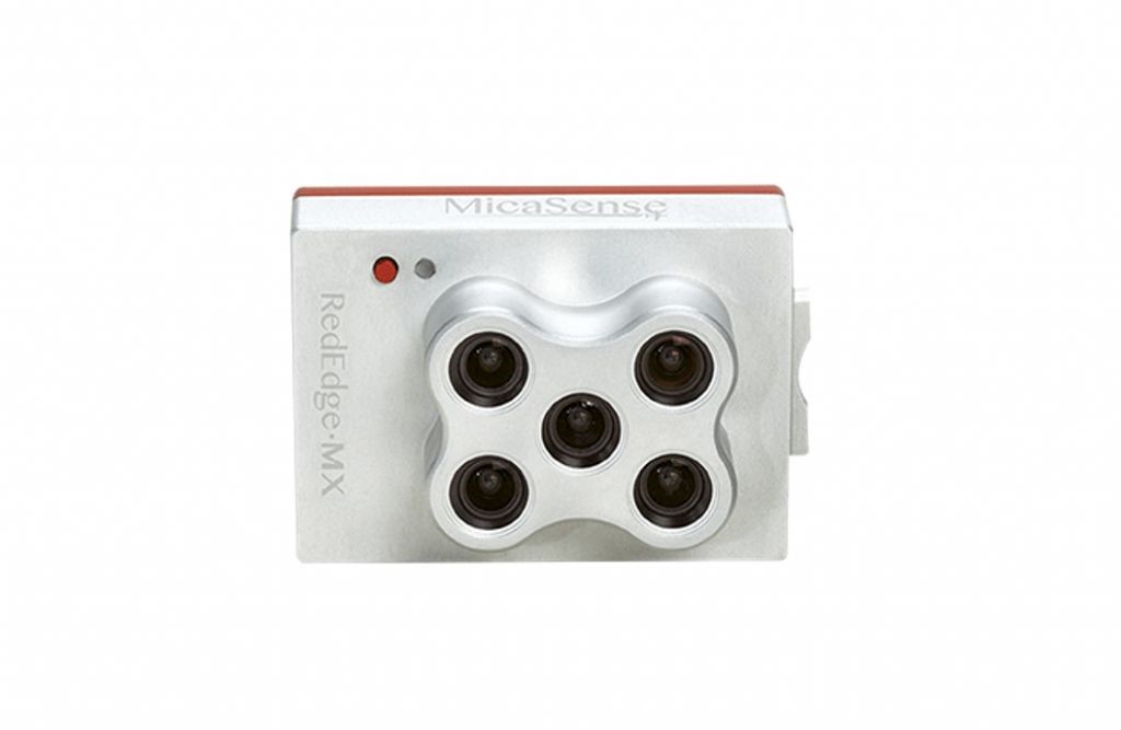
At this moment UgCS Mapper Tools supports the following camera models:
Camera Vendor | Camera Model | Special Note |
|---|---|---|
Micasense | RedEdge-M | |
Micasense | RedEdge-MX |
The result of each shot is a set of 5 images in TIFF format. This set is named capture. Each of 5 images contain data of specific light specter.
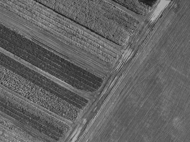
The mission objective is to make a flat map (orthomosaics) from the entire set of all taken photos.
LIght bandsThe output map is expected to contain 3 selected bands of a light specter. This is enough for the most of practical tasks. The common use in agriculture may be:
- Red, Green, Blue - 3 visible bands
- Red, NIR, RedEdge - very informative for field monitoring
Multi-spectral processing workflow consists of 3 major steps:
- Align source bands with pixel precision
- Convert raw data to radiance or reflectance values
- Reconstruct 3D scene and render flat map
Step 1 - Bands align
Launch UgCS Mapper and go to Settings menu, Tools tab:
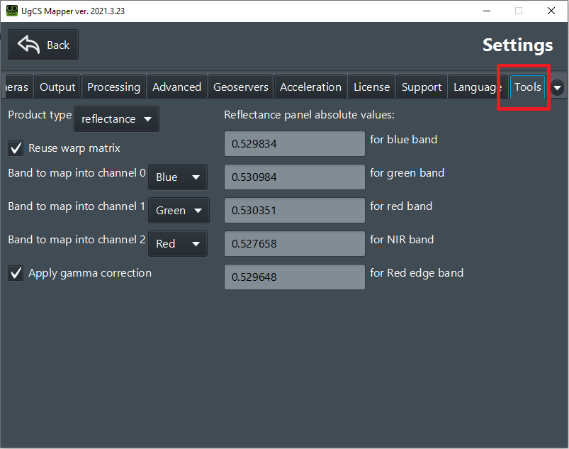
Choose product type: raw for simple visualization or reflectance for vegetation index calculation.
Raw data convertationStep 2 - raw data conversion performed only if the selected product type is not a "raw".
Choose how to map source bands to output channels of aligned JPEGS.
Bands selection hintsIt's possible to choose a single band to be mapped into multiple output channels. For example, required only 2 bands, but the output format has to contain exactly 3 channels. Set Red, Red, NIR files. Or Red, Red, Red is only one is required
Enter referral values for the Lambertian calibration panel if you use one for the reflectance map.
Gamma correction hintsYou can select the "Apply gamma correction" checkbox to perform the gamma correction procedure on aligned images. This will increase the brightness and white balance of result images. They will become close to what the human eye sees.
But this is not advised to do if you want to use result images in calculations of vegetation indices, for example: the real absolute values of reflectance are important for such operations.
Restart UgCS Mapper to apply settings change if any was made and click "Tools" button:
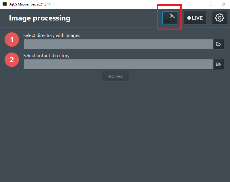
Set source folder with original shots (TIFF format) and destination folder for aligned images (JPEG format) in this dialog:
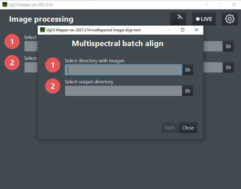
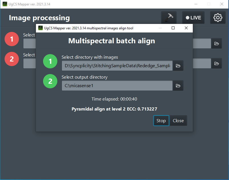
Press the "Start" button and wait for alignment process to complete (message "Processing complete"):
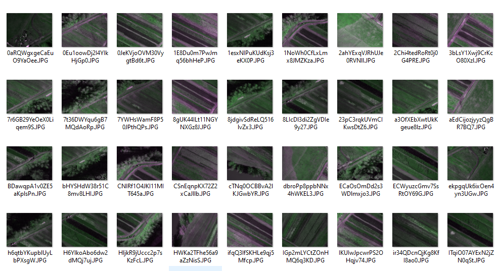
Close align dialog: result files will be present in output folder:
Step 2 - raw data conversion
Automatic conversionConversions are done automatically if "radiance" or "reflectance" product type was selected in settings.
To get correct values for reflected light calibration information is required. This data will be extracted from "calibration shots" which are present in the input folder of alignment process. These shots contain Lambertian calibration panel with reference information:
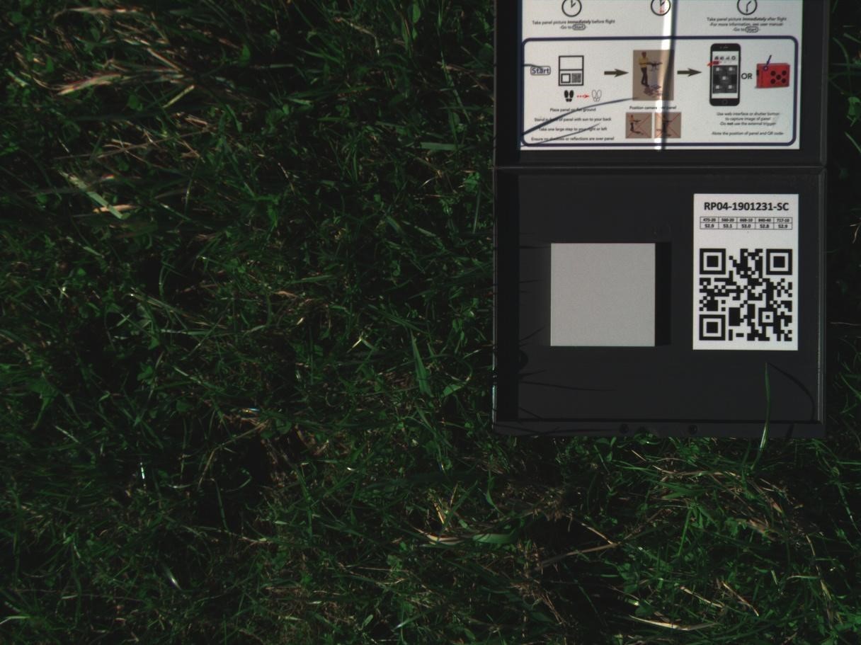
Calibration shots detectionCalibration shots are detected by metadata values in image files. This metadata was generated by using the Micasense camera.
Step 3 - build orthophoto plan
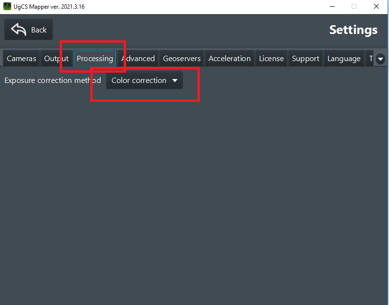
To get precise values, UgCS Mapper have to perform exposure correction. This should be configured in Settings menu on Processing tab. Set COLOR CORRECTION of HISTOGRAM EQUALIZATION value for this option!
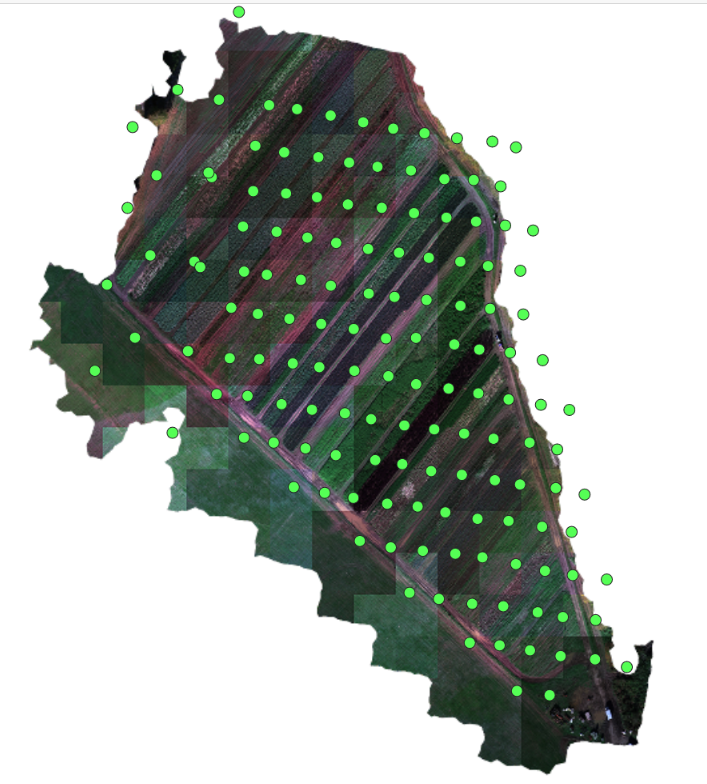
The result without exposure correction
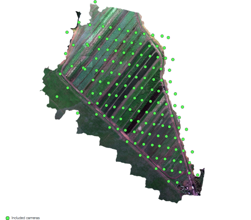
The result with exposure correction set to color correction
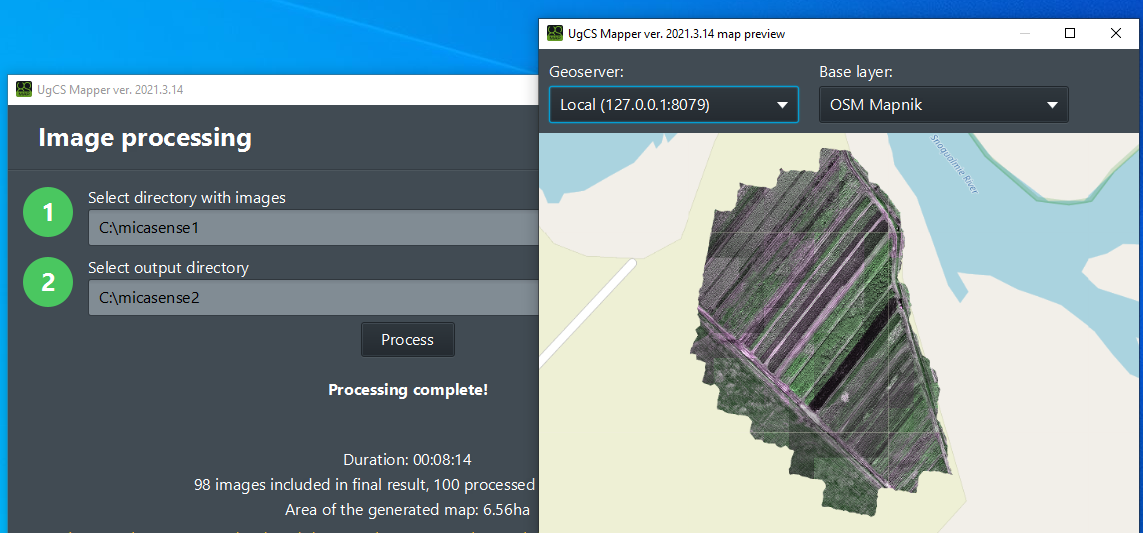
Restart Mapper and go to main dialog. Set source directory to one contains aligned images. And output direction where to save built map.
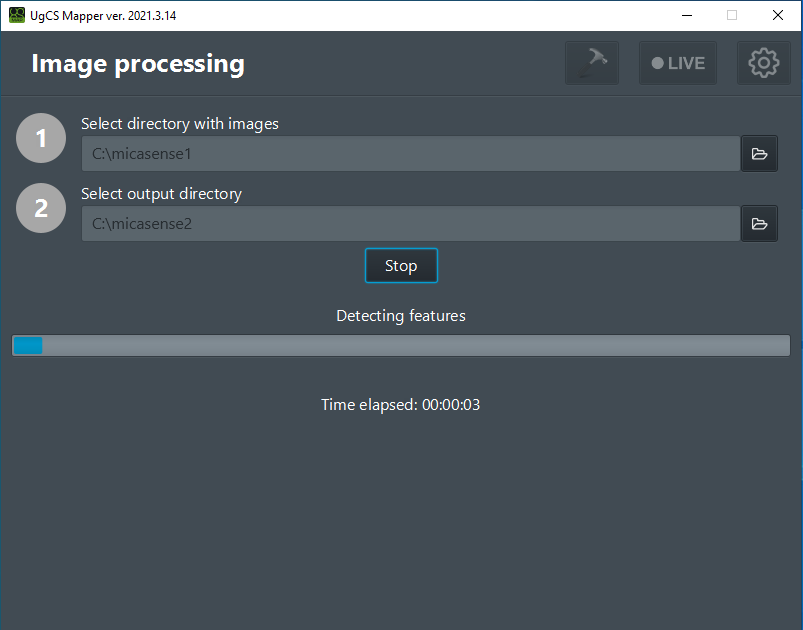
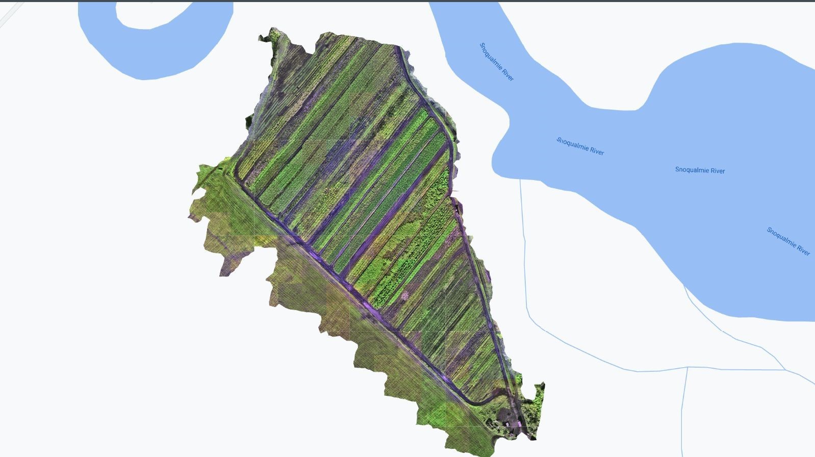
When UgCS Mapper finishes it's work, the resulting GeoTiff map will be available in the output directory:
Here is the sample of the built map over Google maps layer:
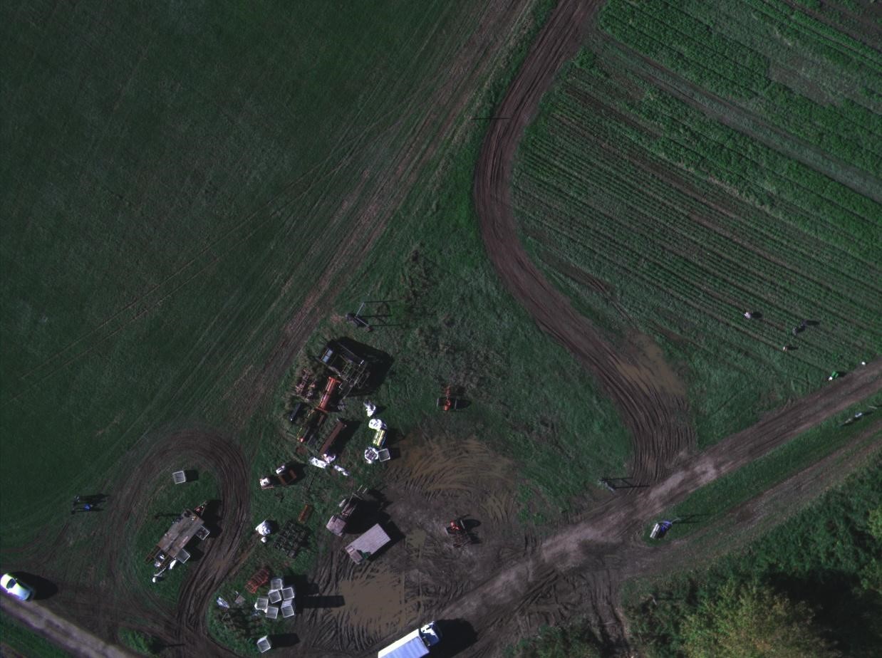
This is the aligned image for visible light bands:
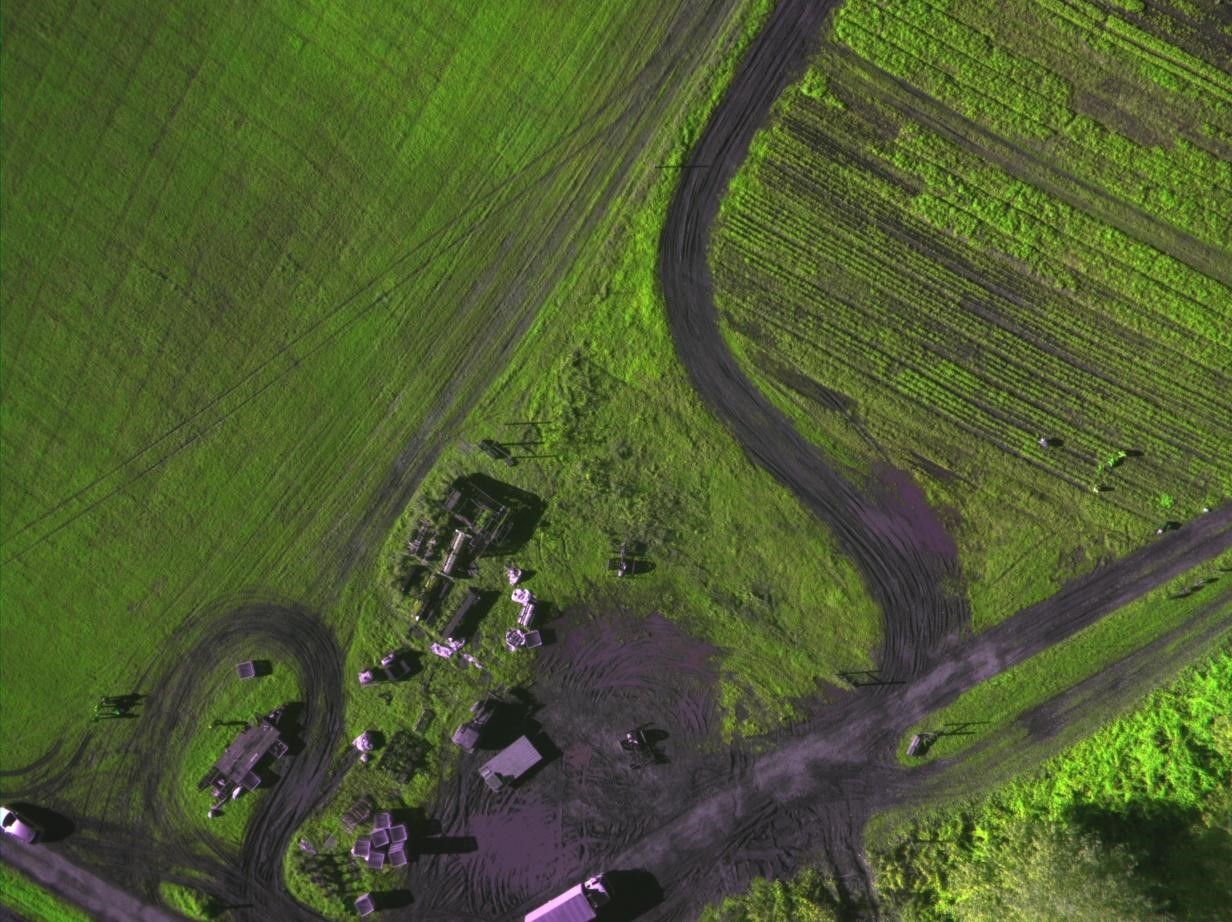
And this is the same area in Red, NIR, RedEdge specter:
Next step is to process 3 band GeoTiff into vegetation index. This can be done with QGIS and raster calculator tool.
Updated 6 months ago
