Video orthophoto processing
Clicking “LIVE” button allows to process orthophoto from prerecorded set of images or from life video stream:

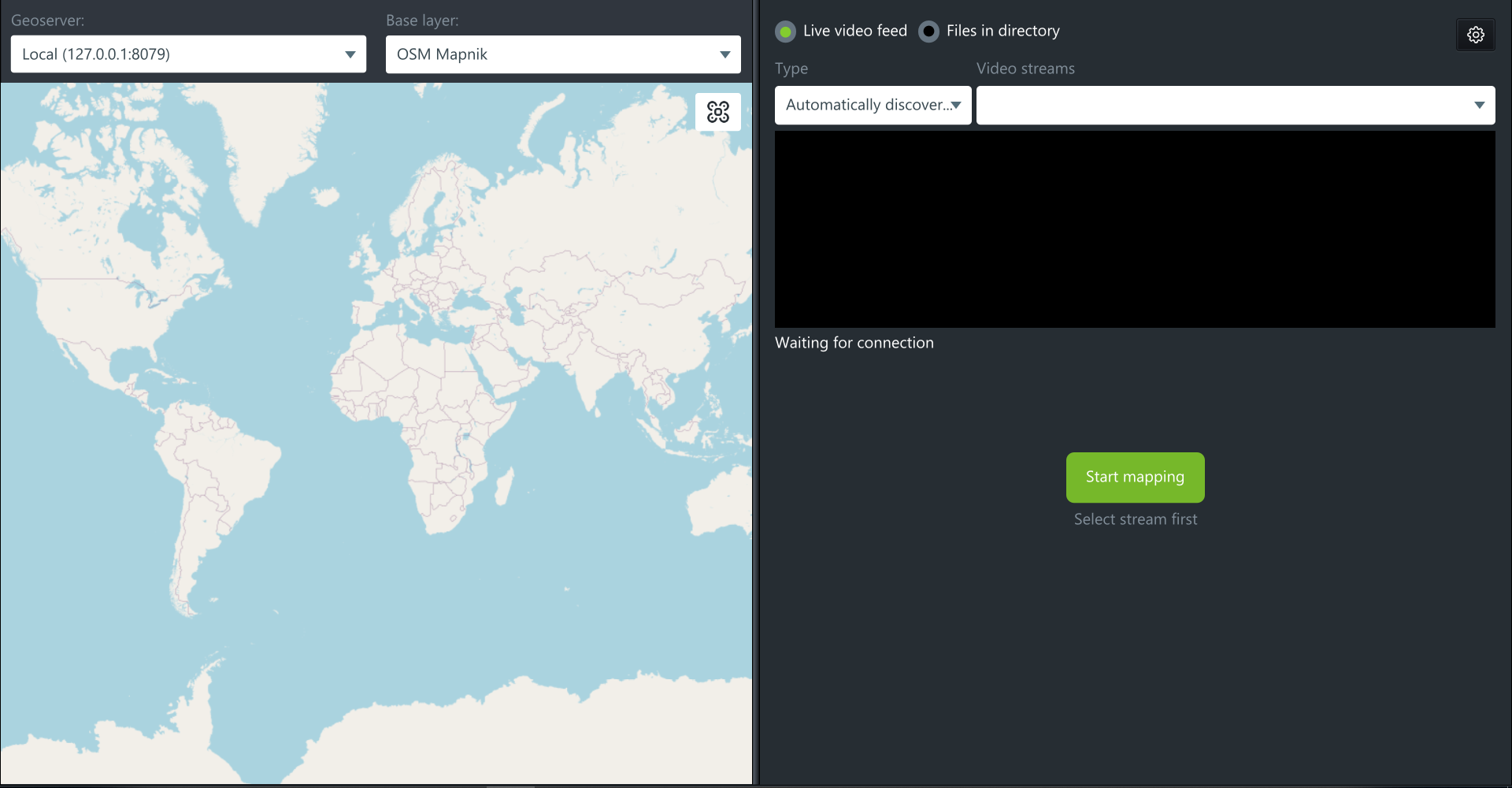
The new window will be displayed:

To start mapping from the drone’s life stream, select “life video feed”

Select “Automatically discovered video stream” and select the drone (drop down menu to the right) from which the video should be streamed.
Note that life video stream should be successfully enabled in UgCS for DJI

It is also possible to specify video server and select the required stream:

Or Manually specify stream URL

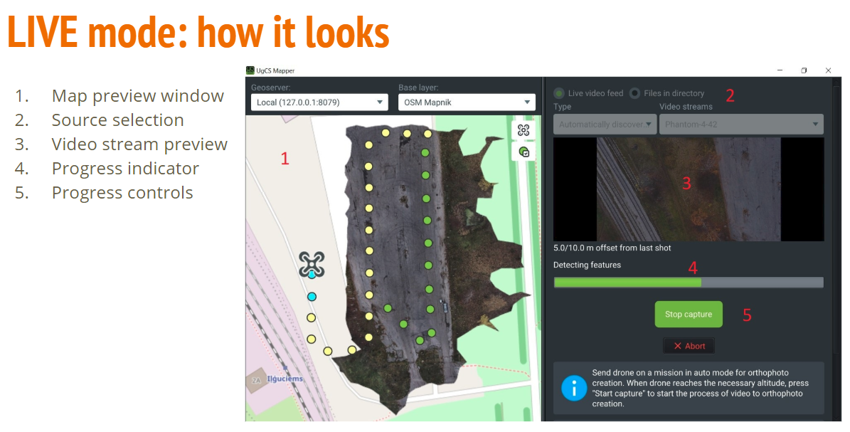
During the mapping process, the images will be taken from the drone and displayed on the left side of the screen with a slight time delay.

Geoserver tab, indicates currently selected geoserver.
Base layer tab, indicates the selected map provider. Any custom layers from UgCS will be displayed in this tab along with preinstalled maps.
Advanced Video settings
Click the “gear” button while in the “live” mode to open settings menu.

Cameras
Cameras – The location of the calibrated cameras and preinstalled camera profiles, can be highlighted by right-clicking and clicking “Set uncalibrated” button to reset calibration settings.
Geoservers
This tab is used to indicate the server address the data is being sent to. By default, is set to local computer. To change it, click “Add” button and enter the required address.
It’s possible to have several servers added to the list. To edit server address, select it by right-clicking and click “Edit”.
Note: During orthophoto stitching, UgCS Mapper will use the first server in the list. In case it is not available, the warning window will appear asking to select the correct server. During publishing, UgCS mapper will ask first, which server to use.
If you need to configure proxy settings, use Proxy Settings button. See details in Image processing > Geoservers section.
Processing
Log4j configuration file – Part of UgCS Mapper is event viewer settings file. See Appendix 1 for more information.
Workspace directory – temporary video processing folder. UgCS Mapper will use default folder if not indicated by user. Not a mandatory field.
Logs directory – Log folder. UgCS Mapper will use default folder if not indicated by user. Not a mandatory field.
Calibration directory – Temporary camera calibration folder. UgCS Mapper will use default folder if not indicated by user. Not a mandatory field.
LIVE stream directory – Temporary video files folder. UgCS Mapper will use default folder if not indicated by user. Not a mandatory field.
Number of processing threads – UgCS Mapper will use all the processor threads. Lower the number in case lowering resource consumption is required.
Acceleration
The tab is used to enable or disable hardware acceleration features. Only NVidia CUDA 10 compatible GPUs are supported at this time.
Note: In case of hardware issues during orthophoto stitching, turn off the CUDA acceleration and restart the UgCS Mapper.
Advanced
The setting located under this tab is for users with deep understanding of photogrammetry processing. It is not recommended to change them without UgCS support team advise.
Common settings profile – is standard profile used in most cases
CUDA settings profiles – in used for CUDA acceleration with only NVidia CUDA 10 compatible GPUs
Custom settings profile – will be enabled if any of the advanced settings will be changed.
Note: Switching between profiles can be done at any time.
Support
Settings in this tab are intended for extended troubleshooting information gathering. They are not affecting the processing result and are not supposed to be change in regular use.
Save error report – generates zip file with logs that is supposed to be provided to tech support for investigation
Preserve workspace checkmark is intended to preserve all the temporary files generated by mapper for deep investigation and is only required by the tech support request
Considerations
• It is not recommended to fly backwards. Collect all of the data while drone is moving forward. Most aerial cameras have rolling shutters, that is why mixed forward and backward flight ruins the chances of turning out the task well.
• Collect images at a consistent speed. All images for a set should be collected on as constant speed as it possible. With a rolling shutter, images taken at differing speeds will have different geometries and harm the accuracy of the final files.
• Preprocessing. Images should not be processed to remove lens distortion. Color correction is possible, but make sure the tags are intact.
• Overlap. Along pass and across pass overlap should exceed 70%. More complex scenes require more overlap.
• Exposure time vs speed. Try to keep the ground smear below the GSD value. 15 m/s flight at 1/1000s exposure will allow 1.5 cm GSD.
• Contiguous. All images must share a common boundary. Don't upload non connecting sections or separate of coverage islands.
• Job shape. When doing long, linear works, please, make sure there are at least two passes so there are enough perspectives to reconstruct the scene. Increased overlap will need to be used to make up for the lost width.
• EXIF tag accuracy. Camera GPS Workflow images should have geotag accuracy of less than 10 m and contain elevation values. Also, precision should be reported with at least 3 decimals of seconds precision. In this format - DD:MM:SS.SSS, not in this - DD:MM:SS.000.
• EXIF tags are intact. EXIF tags should not be modified by 3rd party image processing software. The software requires all of the camera tags originally places in the image files. Photoshop, Photos, Photo Manager and lots of other applications are known to corrupt the tags.
• Inclusion area. Be sure to fly over areas that are required on the map. The software cuts the jagged edges off and the best way to make sure something will be included is to fly over it or make sure it is within the interior of the flight path.
• Repeating patterns. Since the processing is based on matching similar features, target areas with repeating patterns, such as roofs or crops, can confuse the application and be the reason of low-quality outputs.
• Terrain. Terrain greatly affects to overlap. If the terrain rises from the nominal overlap planning point, it will be reduced. If the terrain drops from the planning point, it will be increased. Take the high point of the survey area into account.
• Weather conditions. Clouds will affect the amount of light that is available and winds will affect the symmetry of the ground speed from pass to pass.
• Cruising altitude images only. Only images that taken at the cruising altitude should be uploaded into the system. Please, do not upload images from different altitudes, like those taken during ascent and descent.
• Minimize the Inclusion of water because it moves constantly and indiscrete.
• Avoid sun glare and highly reflective surfaces (like roofs of large buildings and wet pavement).
• Use high overlap in trees areas because they are typically in motion and have a lot of fine details.
• Cameras with a super wide field of view or fisheye lens are not suitable for mapping applications.
• Avoid overexposed and underexposed Images. It is recommended to surveillance the area ahead and take some exposure test images to determine the values that will work.
• If objects in the scene are moving, the processing gets confused and can generate positional errors.
• Do not attempt to stitch vertical surfaces.
• Any images that include the horizon should be kept out of the upload list.
• Only Nadir (straight down) images should be used.
• Avoid mapping late in the day when the sun is low and the shadows are long.
Updated 6 months ago
